RTD Theory
Resistance temperature detectors or RTD’s as they are more commonly known, are another
common way to measure temperature. RTD’s were developed in Europe about a century
ago but have only become popular in the United States in the last 25 years. RTD’s
are very similar in appearance to thermocouples but they function completely different.
As you may remember, thermocouples produce a very small voltage when heated. An
RTD does not produce any voltage and so it relies on an instrument for power. RTD’s
are electrical resistors that change resistance as temperature changes. With all
common types of RTD’s, the resistance increases as the temperature increases. This
is referred to as a
positive temperature coefficient.
Materials of Construction
RTD’s are manufactured using several different materials as the sensing element.
The most common by far is the Platinum RTD. Platinum is used for several different
reasons including high temperature rating, very stable, and very repeatable. Other
materials used to make RTD’s are nickel, copper, and nickel-iron. These materials
are becoming less common now that the cost of platinum RTD’s is coming down.
Construction
RTD’s are manufactured in 3 basic types of construction. Each of these different
types has advantages and disadvantages.
Platinum Thin Film RTD
The thin film style of RTD is probably the most popular design because of their
rugged design and low cost. The thin film element is manufactured by coating a small
ceramic chip with a very thin (.0001”) film of platinum and then laser cutting or
chemical etching a resistance path in the platinum film. The element is then coated
with a thin layer of glass to protect it from harmful chemicals and gases. Larger
extension lead wires are spot welded to the chip and this junction is then covered
with a drop of epoxy to help hold the wires to the element.

Inner Coil Wire Wound RTD
This type of element is normally manufactured using platinum wire. Very small platinum
wire (.0002”) is coiled and then slid into a small 2 hole ceramic insulator. Larger
extension leads are then spot welded to the ends of the platinum wire and cemented
in place. Some manufacturers backfill the bores of the insulator with ceramic powder
once the coils have been inserted. This keeps the coils from moving and shorting
against each other. The end opposite the extension leads is capped with ceramic
cement also.

Outer Wound RTD Element
The outer wound RTD element is made by winding the sensing element wire around a
center mandrill, which is usually made of ceramic. This winding is then coated with
glass or some other insulating material to protect and secure the windings. The
winding wires are then spot welded to extension leads and secured to the body with
ceramic cement or epoxy. .

Each of the types has their advantages. The thin film is the least expensive to
manufacture and also the most rugged. They also can be manufactured in very small
sizes. The inner coil wire wound style is the most accurate. It is however, more
expensive to manufacture and does not perform well in high vibration applications.
The outer wound element is similar in cost to the inner coil element. It is not
as accurate as the inner coil style but is more rugged.
Function
To use an RTD, a small voltage is passed through the element and then measured.
The resistance of the element reduces the voltage and this voltage drop can be converted
into a temperature measurement. With most RTD’s, the higher the temperature, the
higher the resistance. The following diagram represents a simple 2-wire RTD circuit.
An instrument is hooked to one red wire and sends a voltage thru that red wire,
through the element and back thru the other red wire. This reading is then converted
to a temperature by the instrument. The only problem with this simple 2-wire circuit
is that you read the resistance of the lead wire along with the resistance of the
element. There is no way to separate the three resistances.

The 3-wire circuit does allow for compensation of lead wire resistance, which
is normally done by the measuring instrument. The instrument measures the resistance
between the red and the white leads and then subtracts the resistance between the
two reds.
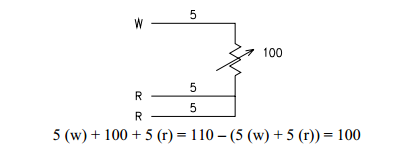
The problem with the 3-wire circuit is that the formula assumes that all
three wires are the same resistance. This is not a problem on short lead wire lengths
but can become a problem as the length of the extension lead wires increases. The
4-wire circuit is a true 4- wire bridge circuit that eliminates any differences
in lead resistances. The 4-wire bridge circuit eliminates lead wires resistance
electrically instead of mathematically.

Element Resistances
RTD’S are manufactured with a base resistance at some temperature point. This temperature
is most commonly 0°C (32°F). The most common base resistance is 100 ohms, which
means that if the RTD is at 0°C, the resistance would be 100 ohms. There are other
resistances and temperatures. Some of these are:
|
10 ohm copper @ 25°C
|
1000 ohm platinum @ 0°C
|
|
200 ohm platinum @ 0°C
|
604 ohm nickel/iron
|
|
500 ohm platinum @ 0°C
|
Temperature Coefficient
Another common term used with RTD’s is temperature coefficient. This refers
to the change in resistance vs. change in temperature. There are 2 common coefficients
for platinum RTD’s’ and several others for the copper and nickel types. The most
common platinum RTD has a temperature coefficient of .00385 ohms/ohms/°C. This means
that a 100 ohm platinum RTD will increase in resistance .385 ohms for every 1°C
increase in temperature.
Temperature Rating
The maximum temperature rating for RTD’s is based on 2 different factors. First
is the element material. Platinum RTD’s can be used as high as 650°C (1202°F). Other
materials are much lower in temperature rating and vary from material to material.
The other determining factor for temperature rating is probe construction. SensorTec
offer three different constructions for maximum temperatures of 200°C (392°F), 450°C
(842°F) and 650°C (1202°F). There are construction considerations used in each of
these different styles making them ideal for use in each of those ranges. No one
style is good for all ranges.
RTD Tolerances
The tolerance or accuracy for RTD sensors is stated at one point only, which is
usually 0°C (32°F). ASTM publications recognize 2 grades of platinum RTD elements
while DIN (Europe’s version of ASTM) recognizes 2 classes of elements. They are
as follows:
ASTM E-1137 grade B = ± .10% @ 0°C (32°F)
ASTM E-1137 grade A = ± .05% @ 0°C (32°F)
DIN 43760 class B = ± .12% @ 0°C (32°F)
DIN 43760 class A = ± .06% @ 0°C (32°F)
RTD Extras
RTD’s are generally more expensive to manufacture or purchase than thermocouples.
Since the RTD circuit is just a resistance circuit, no special extension leadwires
or connectors are required making this portion of the circuit less expensive than
that of a thermocouple
Although some types of RTD elements are rated to fairly high temperatures (650°C
(1202°F)), they become quite fragile at temperatures above 320°C (600°F). A RTD
sensor will not hold up well at these elevated temperatures if there is any vibration
present.
The tolerance or accuracy of an RTD generally decreases as temperature increases.